
What Power Cable Size Do I Really Need?
Views: 0 Author: Site Editor Publish Time: 2026-08-25 Origin: Site


Incorrect wire sizing introduces compounding risks to any electrical installation. Undersizing a conductor leads to catastrophic thermal failures, melted insulation, and severe voltage drops that stall equipment. Oversizing inflates project costs, complicates conduit routing, and creates termination bottlenecks at the equipment panel. Engineers and procurement teams face a constant balancing act. You must meet continuous load requirements, withstand environmental stressors, and maintain strict regulatory compliance without over-engineering the final solution.
Guesswork has no place in electrical design. Relying solely on basic ampacity charts often results in critical field failures. You need a systematic, evidence-based framework to calculate the precise gauge required for your specific application. This applies to standard industrial routing just as much as it does to high-demand continuous loads. By evaluating load limits, distance, thermal ratings, and termination constraints, you can specify the exact conductor needed for safe, efficient operation.
Key Takeaways
Ampacity is only the baseline: Selecting a gauge based solely on maximum amperage ignores the critical impact of voltage drop over extended distances.
Insulation dictates performance: The thermal rating of the jacket (e.g., standard PVC vs. cross-linked polyolefin) directly impacts the cable's safe current-carrying capacity in enclosed spaces.
Application-specific shielding matters: High-voltage or data-adjacent environments require specific interference mitigation, making the choice between shielded and unshielded variants a critical safety and operational decision.
Compliance is non-negotiable: Adhering to NEC (National Electrical Code) or IEC standards for continuous loads (like the 80% rule) prevents compliance failures and liability during safety audits.
The Fundamentals of Power Cable Sizing (AWG vs. SWG)
Establishing a standardized measurement baseline is an absolute necessity before calculating any load requirements. Without a unified understanding of wire gauge standards, design specifications easily fall apart during procurement. You must know exactly how your conductors are measured and classified before ordering materials.
AWG vs. SWG Standards
The American Wire Gauge (AWG) system operates on an inverse relationship based on the wire drawing process. A smaller AWG number indicates a larger physical wire diameter. For example, a 4 AWG conductor is significantly thicker than a 10 AWG conductor. This system dominates North American manufacturing and installations.
Conversely, the British Standard Wire Gauge (SWG) is common in other parts of the world. While SWG also uses an inverse numbering system, the actual physical dimensions differ from AWG. This creates a severe procurement risk in international supply chains. Confusing the two can lead to dangerous undersizing if you expect SWG thickness but receive AWG dimensions. Always verify the exact standard when specifying a power cable for international projects.
Gauge Number | AWG Cross-Sectional Area (mm²) | SWG Cross-Sectional Area (mm²) | Variance Risk |
|---|---|---|---|
10 | 5.26 | 8.30 | High (AWG is 36% smaller) |
8 | 8.37 | 13.00 | High (AWG is 35% smaller) |
6 | 13.30 | 20.70 | High (AWG is 35% smaller) |
4 | 21.20 | 32.20 | High (AWG is 34% smaller) |
How Wire Gauge is Measured
Measuring solid wire is straightforward using a standard caliper. Measuring stranded wire requires a specific mathematical approach. You cannot simply measure the overall outer diameter of the stranded bundle, as this includes empty air gaps between the individual copper strands.
To measure stranded wire accurately in the field:
Strip back the insulation to expose the bare copper bundle.
Isolate a single bare strand from the bundle.
Measure the diameter of this single strand using a micrometer in thousandths of an inch (mils).
Square that measurement to calculate the circular mils (cmil) of the single strand.
Multiply that cmil value by the total number of strands in the conductor.
Compare the total aggregate cmil to a standard gauge chart (like NEC Chapter 9, Table 8) to find the true AWG size.
Standard Gauge Baselines
Understanding residential and light-commercial baselines provides a helpful reference point before scaling up to heavy industrial loads. Standard building codes dictate strict minimums for common circuits based on standard 60°C or 75°C insulation ratings.
14-gauge wire serves 15-amp circuits, primarily used for basic lighting routing.
12-gauge wire handles 20-amp circuits, standard for wall receptacles and light appliances.
10-gauge wire supports 30-amp circuits, typically feeding water heaters or heavy-duty air conditioners.
8-gauge wire manages 40-amp circuits, often used for electric ranges and small subpanels.
6-gauge wire carries 55 to 65 amps, standard for large residential subpanels and heavy machinery feeds.
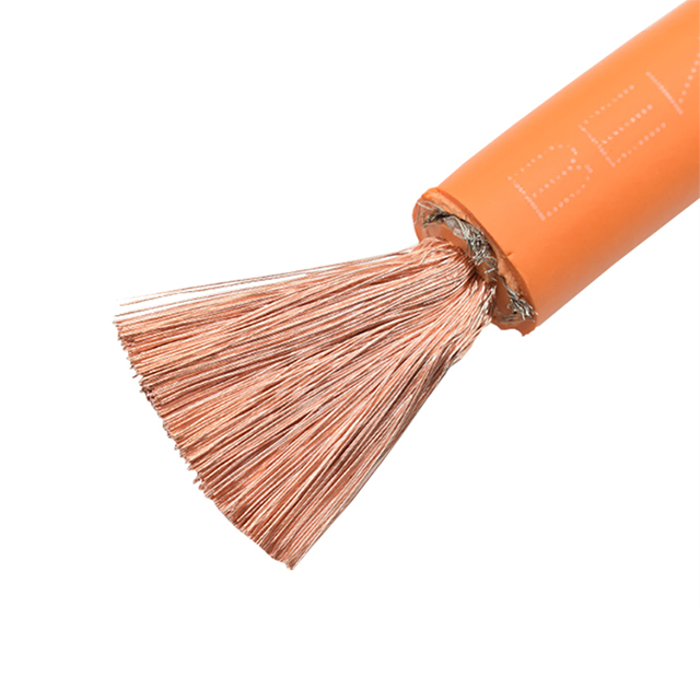
Core Evaluation Dimensions for Power Cable Selection
Selecting the right gauge requires evaluating three distinct dimensions: amperage limits, voltage drop over distance, and thermal constraints. Ignoring any single dimension compromises the entire installation and guarantees an eventual failure.
Amperage Load and Ampacity Limits
Ampacity defines the maximum current a conductor can carry continuously without exceeding its temperature rating. You must first distinguish between continuous and non-continuous loads. A continuous load operates for three hours or more at maximum current.
The National Electrical Code (NEC) mandates the 80% rule for continuous operation. A circuit breaker and its corresponding wire can only be loaded to 80% of their maximum rating for continuous loads. If your industrial heater draws a continuous 80 amps, you cannot use a wire rated for exactly 80 amps. You must size the circuit for 100 amps (80 / 0.80 = 100) to prevent insulation degradation and thermal runaway inside the conduit.
Scalability: Voltage Drop Over Distance
Resistance compounds over distance. Even if a wire handles the amperage perfectly over a one-meter run, that same wire might fail over a 100-meter run due to voltage drop. As current travels through the copper, natural resistance converts some electrical energy into heat, reducing the voltage reaching the equipment.
Consider a 24V stepper motor requiring a 10-meter cable run. A slight voltage drop might reduce the supply to 21V, causing the motor to stall or lose steps. In a 100-meter industrial feed at 480V, a 10% drop forces motors to draw more current to compensate, leading to overheating and premature failure.
The standard formula for calculating single-phase voltage drop is:
Voltage Drop = (2 × Length × Resistance × Current) / 1000
For three-phase systems, the formula adjusts slightly to account for the phase angle:
Voltage Drop = (1.732 × Length × Resistance × Current) / 1000
Industry standards establish strict acceptable loss thresholds. You should aim for a maximum 3% voltage drop for branch circuits (from the panel to the equipment) and a maximum 5% total drop for feeder circuits (from the main service to the subpanel). If your calculation exceeds these thresholds, you must upsize the wire gauge, regardless of the baseline ampacity rating.
Thermal Ratings and Ambient Temperature Adjustments
A wire's ampacity rating assumes a specific ambient temperature, usually 30°C (86°F). When you route cables through hot environments—like factory ceilings, boiler rooms, or outdoor conduits exposed to direct sunlight—the ambient heat reduces the cable's ability to dissipate its own internally generated heat.
You must apply ambient temperature derating factors. If a wire is rated for 100 amps at 30°C, it might only safely carry 82 amps at 45°C. Furthermore, routing multiple current-carrying conductors through a single conduit restricts airflow. The NEC requires conduit fill derating. If you bundle more than three active conductors in a single pipe, you must reduce their allowable ampacity to prevent trapped heat from melting the insulation.
Number of Conductors in Conduit | Ampacity Derating Factor (Multiplier) |
|---|---|
1 to 3 | 1.00 (No derating) |
4 to 6 | 0.80 (80% of original ampacity) |
7 to 9 | 0.70 (70% of original ampacity) |
10 to 20 | 0.50 (50% of original ampacity) |
Specialized Applications: Sizing an EV Charging Cable
Electric vehicle infrastructure represents one of the most demanding electrical environments. These systems push components to their absolute limits, requiring highly specific thermal and ampacity calculations that go far beyond standard commercial wiring.
High-Current Demands in Electric Vehicle Infrastructure
An EV charging cable operates under a worst-case scenario for continuous load. A vehicle might draw maximum amperage for eight to ten hours straight. There is no duty cycle relief. This sustained current generates immense heat, demanding specialized insulation materials that can survive constant thermal cycling without becoming brittle or melting.
XLPO Shielded vs. XLPO Unshielded Cables
Standard PVC insulation degrades rapidly under EV charging conditions. Thermoplastic materials soften when heated and harden when cooled, eventually cracking. Manufacturers utilize XLPO (Cross-linked Polyolefin) instead. The cross-linking process alters the polymer's molecular structure, turning it into a thermoset material. This grants it superior thermal stability, high flexibility in freezing temperatures, and excellent chemical resistance against automotive fluids.
You must choose between shielded and unshielded variants based on the specific installation environment.
An XLPO shielded EV cable is necessary for mitigating electromagnetic interference (EMI). High-frequency switching environments, such as DC fast charging stations or routing paths adjacent to sensitive CAN bus communication lines, generate severe electrical noise. A braided copper or aluminum foil shield captures this interference and routes it safely to the ground, protecting data integrity and preventing vehicle communication faults.
Conversely, an XLPO unshielded EV cable provides a highly cost-effective solution for standard AC routing. When installing basic Level 2 home chargers where EMI is not a risk factor, unshielded cables reduce material costs, decrease overall weight, and simplify the termination process inside the charging pedestal.
Managing Heat Dissipation in Continuous Load Scenarios
DC fast chargers push hundreds of amps at voltages exceeding 800V. Traditional copper conductors sized for these loads would be too heavy and rigid for human use. To manage extreme thermal output while maintaining flexibility, manufacturers utilize liquid cooling. Coolant circulates through tubes integrated directly into the cable jacket, extracting heat from the conductors. This allows a physically smaller gauge to safely carry massive currents without exceeding safe touch temperatures on the outer jacket.
Implementation Risks and Mitigation Strategies
Theoretical calculations often clash with physical installation realities. You must anticipate mechanical constraints and environmental hazards before finalizing your gauge selection and ordering materials.
Termination and Connector Compatibility
Upsizing a conductor to mitigate voltage drop creates a common manufacturing constraint. You might calculate that a 100-meter run requires a 2 AWG wire to keep voltage drop under 3%. However, the standard terminal blocks or lugs on your 50-amp equipment might only accept a maximum of 6 AWG wire. The upsized wire simply will not fit into the hole.
Do not cut away copper strands to force the wire into the lug. This creates a dangerous high-resistance bottleneck that will eventually catch fire. Instead, use proper mitigation tactics. Install reducing pin terminals, which crimp onto the larger wire and feature a smaller solid pin designed to fit the equipment block. Alternatively, use an intermediate splice block near the equipment to transition safely from the large long-run gauge to a short whip of the smaller gauge.
Environmental Factors (Moisture, UV, Chemical Exposure)
Gauge size means nothing if the jacket fails. Improper material selection in harsh environments leads to rapid degradation. Petrochemical plants require oil-resistant jackets. Outdoor solar arrays demand UV-stabilized insulation containing carbon black to prevent sunlight from cracking the outer sheath. Underground direct-burial installations require moisture-resistant ratings (like THWN-2 or XHHW-2) to prevent water ingress from corroding the copper strands.
Flexibility and Conduit Fill Limits
You must weigh the trade-off between solid and stranded conductors. Solid wire is cheaper and slightly more compact, but it is highly rigid. Pulling large-gauge solid wire through conduit bends requires immense labor and risks damaging the insulation against the pipe walls. Stranded wire offers the flexibility needed for complex routing and environments subject to vibration.
Always calculate NEC conduit fill percentages. To prevent physical damage during pulling and ensure adequate airflow for heat dissipation, the NEC restricts how much space wires can occupy inside a pipe. For a conduit containing more than two conductors, the wires cannot occupy more than 40% of the total internal cross-sectional area. Upsizing your wire gauge often forces you to upsize your conduit as well.
Compliance, Certifications, and Safety Standards
Never install uncertified wire. Ensure all materials carry appropriate markings from recognized testing laboratories, such as UL (Underwriters Laboratories), CSA (Canadian Standards Association), or CE markings for European applications. Mitigate your liability by documenting all derating calculations, ambient temperature assumptions, and conduit fill ratios during the design phase. This documentation is critical during safety audits and municipal electrical inspections.
Overall Value Influencing Factors: Conceptual Trade-offs
Engineering decisions rarely exist in a vacuum. You must balance physical performance against budget constraints, material costs, and future scalability.
Copper vs. Aluminum Conductors
Copper offers superior electrical conductivity. It requires a smaller gauge to carry the same current as aluminum, making it easier to route through tight spaces. Copper also resists oxidation better and withstands repetitive bending without fatiguing.
Aluminum provides a distinct weight and cost advantage. It is significantly cheaper than copper and weighs roughly 30% as much. However, aluminum has only about 61% of the conductivity of copper. You must upsize aluminum conductors by one or two gauge sizes to match copper's ampacity. Furthermore, aluminum oxidizes rapidly when exposed to air, creating high resistance at connection points. You must use specific anti-oxidant joint compounds and AL/CU-rated lugs to prevent termination fires.
Property | Copper Conductors | Aluminum Conductors |
|---|---|---|
Conductivity | 100% (Standard Reference) | ~61% of Copper |
Weight | Heavier (Harder to pull) | Lighter (Easier to handle) |
Gauge Requirement | Smaller gauge for same load | Larger gauge for same load |
Termination Risk | Low (Stable connections) | High (Requires anti-oxidant paste) |
Oversizing for Future-Proofing vs. Immediate Budget Constraints
Exact-sizing your conductors saves immediate material and labor costs. However, it limits future expansion. If a facility plans to upgrade equipment in two years, installing a larger conductor initially offers a high return on investment. The cost of pulling wire twice—including labor, downtime, and new conduit—far exceeds the incremental cost of buying a thicker wire on day one. Evaluate the facility's long-term operational roadmap before finalizing the design.
Conclusion
Determine the maximum continuous load of your equipment and apply the 80% rule to establish the baseline ampacity requirement.
Calculate the total run distance and verify the voltage drop remains under 3% for branch circuits using a certified calculator.
Inspect equipment terminal blocks to confirm the maximum accepted wire diameter before finalizing your gauge selection.
Apply ambient temperature and conduit fill derating factors based on the specific physical routing environment.
Select the appropriate insulation material and shielding configuration based on environmental hazards and electromagnetic interference risks.
FAQ
Q: What happens if a power cable is too small for the electrical load?
A: Undersized conductors create excess electrical resistance. This resistance generates heat faster than the jacket can dissipate it. The insulation eventually melts, exposing bare copper. This sequence leads directly to short circuits, equipment damage, or catastrophic electrical fires inside the walls or conduits.
Q: How do I calculate voltage drop for a long power cable run?
A: Use the standard single-phase formula: Voltage Drop = (2 × Length × Resistance × Current) / 1000. Length is in feet, resistance is ohms per 1000 feet, and current is amps. DC systems use the same formula, but DC equipment is often much more sensitive to slight voltage fluctuations.
Q: When should I specify an XLPO shielded EV cable over an unshielded one?
A: Specify shielded cables when electromagnetic interference (EMI) poses a risk. High-frequency switching in DC fast chargers generates noise that can disrupt adjacent data lines, vehicle communication protocols (like CAN bus), or nearby sensitive electronics. Unshielded cables are sufficient for basic residential AC charging.
Q: How do you accurately measure the bare diameter of a stranded wire?
A: You cannot measure the whole bundle. Isolate a single strand and measure its diameter with a micrometer in thousandths of an inch (mils). Square that number to get the circular mils (cmil). Multiply the single strand's cmil by the total number of strands to find the aggregate size.
Q: What is the difference in application between 12-gauge and 14-gauge wire?
A: These are standard residential and commercial baselines. 14-gauge wire is rated for 15-amp circuits and is primarily used for lighting runs. 12-gauge wire is thicker, rated for 20-amp circuits, and is standard for wall receptacles and light appliances.
Q: Does DC voltage require a different cable size than AC voltage?
A: Ampacity rules remain similar, but low-voltage DC systems suffer severe functional consequences from voltage drop. A 2-volt drop on a 120V AC system is negligible. A 2-volt drop on a 12V DC system is a massive percentage loss, frequently necessitating a larger gauge for equivalent distances.


