
What Is a Power Cord and Its Purpose?
Views: 0 Author: Site Editor Publish Time: 2026-07-07 Origin: Site


Treating power delivery as an afterthought invites immediate operational danger. Many businesses view these connections as interchangeable commodities. This oversight introduces serious vulnerabilities. They range from unexpected equipment downtime to catastrophic facility fires. Transitioning from basic assumptions to a structured technical evaluation framework remains essential. You must secure infrastructure by understanding exact electrical demands. Using incorrect cabling often violates local fire codes and voids expensive hardware warranties.
This guide equips procurement and engineering teams with actionable evaluation criteria. We provide the tools needed to specify exact connections. We will explore structural anatomy and decode complex industry standards. We will also highlight critical environmental factors influencing material selection. You will learn how to match wire gauge directly to hardware demands. Ultimately, this knowledge ensures peak hardware performance. It guarantees strict regulatory adherence across any operational deployment environment.
Key Takeaways
A power cord is a detachable or hardwired assembly that safely transmits electrical energy from a primary power source to an appliance or piece of equipment.
Unlike raw bulk cable, power cords are pre-terminated with specific connectors (e.g., NEMA, IEC 60320) matched to regional and hardware standards.
Selecting between different power cord types requires matching wire gauge (AWG), amperage, voltage, and jacket material to the operational environment.
Verification of compliance standards (UL, CSA, RoHS) is mandatory to mitigate implementation risks and ensure facility safety.
The Anatomy of a Power Cord: Beyond Basic Electrical Wire
To understand proper selection, you must differentiate a finished product from raw materials. Many buyers confuse a finished assembly with standard electrical wire. Raw spools require manual cutting, stripping, and hand termination before use. Conversely, a finished assembly arrives ready for immediate, safe connection. It integrates several highly engineered layers into a single cohesive unit. Each component plays a distinct role. They work together to bridge the gap between grid power and sensitive electronics safely.
Conductors: Manufacturers rely heavily on stranded copper cores. Stranding offers necessary flexibility for tight routing. It also maintains excellent electrical conductivity. Solid copper breaks easily under repeated bending. Stranded variations prevent internal fractures during physical movement. Higher strand counts yield greater flexibility for compact spaces.
Insulation: Specialized dielectric materials coat each individual copper strand. These layers prevent dangerous short circuits. They isolate phase, neutral, and ground pathways. Engineers use standard color codes to identify specific functions. North American codes typically use black for hot, white for neutral, and green for ground.
Outer Jacket: This protective layer serves as the primary environmental defense mechanism. It shields internal components from physical abrasion. It repels harsh chemicals and withstands extreme temperatures. Thick jackets prevent crushing impacts in heavy foot-traffic zones.
Shielding (Optional): High-end assemblies often include metallic foil or braided copper shielding. This layer blocks electromagnetic interference (EMI). Medical facilities and broadcast studios rely on shielded cables to protect sensitive signal integrity.
Terminations/Connectors: The assembly features factory-molded ends. The plug securely connects to wall receptacles. The opposite female receptacle interfaces directly into device hardware. Factory overmolding ensures airtight seals. It prevents moisture ingress and eliminates mechanical strain at vulnerable connection points.
Faulty terminations cause numerous electrical failures in commercial settings. Factory-molded connectors eliminate human error during installation. They guarantee consistent contact pressure across all internal pins.
Standard Power Cord Types and Connector Frameworks
Navigating global connectivity requires deep understanding of regional standards. Solution categories map directly to specific commercial and industrial requirements. You must align your hardware with the exact socket topology present at the deployment site. Exploring various power cord types prevents costly project delays. Engineers rely on two primary frameworks. They standardize connections across borders and industries.
IEC 60320 Standards (Global IT & Hardware)
The International Electrotechnical Commission (IEC) 60320 standard governs global IT hardware. These connectors utilize a universal mating system. A highly common pairing is the C13/C14 combination. You see this configuration on desktop computers and basic server racks. The C14 inlet accepts the C13 connector perfectly. They generally handle up to 10 or 15 amps depending on regional voltage.
For higher energy demands, data centers deploy the C19/C20 pairing. These rectangular connectors handle up to 20 amps. They power high-density blade servers and enterprise network switches effortlessly. Laptops often utilize the smaller C5/C6 "Mickey Mouse" design or the two-prong C7/C8 "Figure-8" configuration.
NEMA Standards (North American Infrastructure)
North American infrastructure relies on the National Electrical Manufacturers Association (NEMA). NEMA nomenclature indicates specific voltage and amperage limits. It also dictates structural design. For example, a NEMA 5-15P represents a 125-volt, 15-amp plug. The number "5" denotes the voltage class. The "15" represents maximum amperage. The "P" denotes a male plug, while "R" stands for receptacle.
Standard consumer setups utilize straight-blade designs. They push in easily and disconnect quickly. Industrial environments demand stronger, fail-safe connections. They utilize specialized locking variants. A NEMA L6-30P uses a robust twist-lock mechanism. The "L" stands for locking. It requires insertion and a firm twist to secure into place. This prevents accidental disconnections during heavy machinery vibrations.
Connector Framework Comparison Chart
Standard Category | Common Designation | Typical Amperage | Primary Application |
|---|---|---|---|
IEC 60320 | C13 / C14 | 10A - 15A | Desktop PCs, Monitors, Standard IT racks |
IEC 60320 | C19 / C20 | 16A - 20A | High-density servers, Enterprise switches, UPS systems |
NEMA (Straight) | 5-15P | 15A | Standard North American wall outlets, Office equipment |
NEMA (Locking) | L6-30P | 30A | Industrial machinery, Heavy vibrations, Factory floors |
Jacket Materials and Environmental Application Matching
Electrical capacity only solves half the engineering problem. You must match the outer jacket to physical deployment realities. Evaluation dimensions focus heavily on material science. Industry lettering decodes exactly what environments a specific jacket can survive. Underwriters Laboratories created this lettering system for easy identification.
Decoding Common Designations
Common designations include SJT, SVT, and SOOW. We can decode these letters easily to understand capabilities. "S" stands for Service, which indicates a heavy-duty 600V rating. "J" indicates Junior service, carrying a 300V rating. "T" signifies Thermoplastic, typically PVC material. "O" indicates Oil-resistant outer layers. "OO" means both jacket and inner insulation resist oil. "W" signifies Weather and Water resistance.
Specific Use-Cases and Material Selection
Data centers and typical offices utilize SJT jackets. These PVC coatings work perfectly in controlled indoor environments. They handle low-abrasion scenarios effectively. They remain highly cost-effective and sufficiently flexible for standard rack routing. However, they do not survive well under chemical exposure or freezing temperatures. PVC turns brittle and cracks in sub-zero environments.
Harsh industrial spaces require elastomer or rubber jackets. SOOW variants provide heavy-duty environmental defense. They resist cutting oils, factory chemicals, and frequent water immersion. Rubber compounds retain high flexibility even in extreme cold. They handle constant dragging across rough concrete workshop floors without tearing.
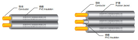
Niche architectural layouts demand highly specific cable profiles. For low-profile, light-duty internal applications, contractors might specify an SPT PVC parallel cord for building wiring. The "SPT" designation indicates a stranded parallel thermoplastic construction. Its distinct flat design routes cleanly inside specialized enclosures. It tracks seamlessly along tight baseboards. It supplies low-draw devices efficiently. Always verify local fire and electrical codes before utilizing parallel cords for integrated structural wiring. Some local jurisdictions restrict their use strictly outside of finished walls.
Decision Stage: How to Specify the Right Power Cord
Transitioning from theoretical frameworks to active purchasing requires structured evaluation. We use a clear features-to-outcomes framework. This approach narrows down product shortlists based on precise electrical mathematics. You must avoid guesswork when procuring electrical infrastructure.
Evaluate Wire Gauge (AWG) vs. Amperage: The American Wire Gauge system utilizes an inverse relationship. Smaller numbers indicate thicker copper wires. Thicker copper handles much higher amperage safely. For example, 18 AWG generally handles 10 amps, while 14 AWG handles 15 amps. Running a continuous 15-amp load through a thin 18 AWG cord introduces severe risks. The restricted copper creates high electrical resistance. The wire rapidly overheats and melts the surrounding insulation. This frequently sparks catastrophic electrical fires. Always match the gauge directly to peak device draw. Apply the 80% rule for continuous loads. Never exceed 80% of the maximum rated capacity for devices running longer than three consecutive hours.
Verify Voltage Ratings: Jacket insulation must safely contain the intended circuit voltage. Most commercial products support either 125V or 250V configurations. Industrial settings often require robust 300V or 600V ratings. Voltage mismatch causes dielectric breakdown. This failure allows electricity to arc outside the cable boundaries. It creates immediate shock hazards for nearby personnel.
Calculate Length and Voltage Drop: Overall length impacts power delivery efficiency significantly. Electrical current loses force as it travels over long distances. Excessive length creates a measurable voltage drop. If sensitive IT equipment receives inadequate voltage, internal power supplies overwork themselves. They draw more current to compensate. This increases internal heat generation. It drastically shortens the lifespan of expensive servers. Keep cable runs as short as practically possible. Avoid daisy-chaining multiple extensions together.
You must specify a power cord that balances length, wire gauge, and insulation perfectly. Under-specification always leads to hardware damage. It drastically increases the probability of workplace safety incidents.
Compliance, Safety, and Implementation Risks
Purchasing uncertified electrical components introduces massive liability into your organization. Authoritative safety standards serve as non-negotiable baselines for enterprise procurement. Certified testing prevents dangerous manufacturing shortcuts. Global agencies test these products against extreme thermal and physical stress.
Authoritative Standards and Certifying Bodies
Always look for accredited laboratory marks stamped directly on the jacket. North American markets rely heavily on UL (Underwriters Laboratories) and CSA (Canadian Standards Association). European markets mandate CE markings. They also enforce the RoHS directive, which strictly limits hazardous substances like lead and cadmium. These symbols confirm rigorous physical stress testing. UL conducts intense flame tests, like the VW-1 rating, to ensure materials self-extinguish during emergencies. Selecting ISO 9001 certified manufacturers further guarantees consistent production quality.
Navigating Implementation Risks
Implementation risks threaten daily operations if ignored. Spotting counterfeit materials requires active vigilance. Fraudulent manufacturers often hide dangerously undersized copper within deceptively thick plastic jackets. Always weigh your incoming cables. Unusually light assemblies often lack sufficient internal copper stranding. This poor construction leads to rapid overheating under moderate loads.
Thermal degradation poses another invisible, yet critical, threat. Coiling long runs under heavy electrical load concentrates heat. The overlapping layers prevent natural thermal dissipation. This phenomenon melts internal insulation rapidly and causes spontaneous shorts. Never bundle high-draw connections tightly together using zip ties. Allow proper airflow around all active wiring.
Regulatory mismatches also plague global hardware rollouts. Connecting a cord rated only for 110V into a 220V grid causes immediate component failure. Insulation rated for 125V cannot contain a 250V surge. You must audit target destination grids carefully before shipping hardware internationally.
Conclusion
Specifying electrical assemblies requires careful alignment of several technical variables. You must balance physical connectors with accurate load capacities. You also must consider the ambient deployment environment. Overlooking any single factor jeopardizes expensive hardware and threatens personnel safety. An informed approach transforms risky assumptions into reliable infrastructure planning.
Consider these actionable next steps for your procurement teams:
Audit all equipment power requirements before placing bulk hardware orders.
Review manufacturer specification sheets to confirm exact AWG sizing and jacket material ratings.
Implement strict internal policies prohibiting the daisy-chaining of temporary extensions.
Consult exclusively with certified manufacturers or authorized distributors.
Request application-specific quotes that guarantee verifiable UL, CSA, or CE compliance.
Taking these deliberate actions ensures seamless operation. It secures safe, continuous power delivery across your entire facility infrastructure.
FAQ
Q: What is the difference between a power cord and a power cable?
A: The main semantic difference revolves around flexibility and termination. Cords typically feature highly flexible, stranded copper. They act as pre-terminated assemblies for temporary or appliance-level connections. Conversely, cables usually refer to rigid, bulk-spooled wiring. Electricians hardwire cables directly into facility infrastructure to handle much higher transmission voltages.
Q: How do I know what AWG power cord I need?
A: You must calculate your device's maximum current draw. Find the wattage on the equipment's data plate and divide it by the supply voltage to determine amperage. Generally, 18 AWG handles up to 10 amps, 16 AWG supports 13 amps, and 14 AWG safely carries 15 amps. Always consult standard ampacity charts.
Q: Can I use an indoor power cord outdoors?
A: No. Indoor jackets degrade rapidly when exposed to environmental elements. UV rays crack standard PVC, allowing moisture to reach active conductors. You must specify outdoor-rated assemblies. These feature specialized weather-resistant elastomers and UV inhibitors that maintain integrity through rain, snow, and direct sunlight exposure.
Q: Why do some power cords have two prongs and others have three?
A: The third prong serves as a dedicated grounding pathway. It diverts stray electrical current away from the user during a fault. Three-prong designs are vital for metal-cased equipment. Two-prong versions lack this ground because the connected appliance utilizes internal double-insulation, eliminating the risk of exterior chassis shocks.


