
IEC Power Cord Types C13 C15 C19 Explained
Views: 0 Author: Site Editor Publish Time: 2026-08-18 Origin: Site


Selecting the wrong cable in enterprise IT or data center environments leads directly to hardware damage, compliance failures, and catastrophic downtime. Facilities managers and network engineers frequently face operational confusion surrounding IEC 60320 standards. The overlapping visual similarities between C13, C15, and C19 connectors mask vastly different thermal tolerances and amperage limits. Using an under-rated cable for a high-density server rack or a high-heat network switch guarantees a thermal event. This often results in electrical fires or melted receptacles.
This guide provides a strict technical evaluation of these core IEC types. We detail their specific engineering specifications, physical mating requirements, and environmental implementation criteria. You will learn how to identify the correct connector for specific hardware loads, evaluate environmental heat factors, and ensure safe, scalable power distribution across your entire infrastructure.
Visual Similarity vs. Technical Reality: C13 and C15 connectors look similar, but the C15 features a specific notch to handle high-temperature environments (120°C) safely.
Amperage Scaling: C13 and C15 are generally rated for 10A to 15A, whereas C19 is engineered for high-density hardware requiring up to 16A (international) or 20A (North America).
Mating Rules: IEC standards dictate that a higher-rated female connector can fit into a lower-rated male inlet, but never the reverse, preventing thermal overload.
Regional Compliance: Global deployments require matching IEC connectors with region-specific plugs, such as a 16A European power cord or specific localized supply cords, to maintain end-to-end compliance.
The IEC 60320 Standard: Framework for Power Cord Selection
Inlet vs. Outlet Terminology
The IEC nomenclature deliberately breaks away from standard consumer phrasing like plug and jack. The standard strictly uses outlet and inlet terminology to define power flow. Odd numbers, such as C13, C15, and C19, represent the female connector. This connector terminates the cable and plugs directly into the device. Even numbers, such as C14, C16, and C20, represent the male inlet. This inlet is physically built into the hardware chassis or power supply unit.
The structural logic behind the standard relies on specific pin configurations, grounding requirements, and physical keying. These design elements physically prevent unsafe connections. A user cannot accidentally force a low-amperage cable into a high-amperage receptacle. Lower-amperage connectors exist within the broader IEC hierarchy to serve lighter loads. Devices like laptops or audio-visual equipment use the C5/C6 or C7/C8 connectors. The heavy-duty C13, C15, and C19 cords sit at the top of the enterprise power hierarchy, managing critical infrastructure loads.
To understand the mating logic, facilities teams must memorize the standard pairings. The female connector always mates with the male inlet one number higher.
Female Connector (Cable End) | Male Inlet (Hardware End) | Typical Application |
|---|---|---|
C13 | C14 | Standard IT servers, basic switches |
C15 | C16 | High-heat PoE switches, core routers |
C19 | C20 | Blade servers, high-density PDUs |
Global Compliance and Voltage Ratings
IEC 60320 standards interact dynamically with regional power grids across the globe. The connectors themselves handle different voltage levels effortlessly. They support 120V deployments in North America and 240V deployments in Europe or Asia. The IEC connector on the equipment side remains standard regardless of the geographic location. This universal design allows hardware manufacturers to ship the exact same server chassis globally.
The wall-side plug must meet strict local certifications. Deploying hardware in international data centers requires matching the universal IEC connector to a localized plug standard. Facility managers must ensure the entire cable assembly carries the correct regulatory stamps for the region. Mixing uncertified wall plugs with enterprise hardware voids warranties and fails local fire safety inspections. You must verify that the copper conductors inside the jacket meet the cross-sectional area requirements for the target region, typically measured in AWG for North America and mm² for international markets.
IEC C13 / C14 Power Cords: The IT Standard
Technical Specifications and Baselines
The C13 connector serves as the absolute baseline for enterprise IT power delivery. Strict specifications govern its deployment and usage limits. The standard rates these connectors for 10A internationally. In North America, the Underwriters Laboratories (UL) rating increases the limit to 15A. The maximum pin temperature strictly caps at 70°C. Exceeding this temperature degrades the internal insulation.
The physical form factor features a standard 3-pin design. It utilizes a rectangular shape with distinct chamfered top corners. This shape ensures proper orientation during installation. The internal conductors typically utilize 18 AWG to 14 AWG wire. The specific gauge depends entirely on the length of the run and the amperage requirements of the deployment. A standard 6-foot cable carrying 15A requires 14 AWG wire to prevent dangerous voltage drops.
Primary Use Cases and Hardware Compatibility
Standard data center deployments heavily rely on the C13 connector. Desktop computers, standard network switches, and basic Power Distribution Units (PDUs) use this standard extensively. Entry-level 1U servers also utilize C13 connections for their primary power supplies. The ubiquity of the C13 makes it the most common cable found in any IT environment.
PDU jumper cords represent a critical use case for rack architecture. C13-to-C14 extension cables connect rack-mounted servers directly to vertical rack PDUs. This method significantly reduces cable clutter compared to running standard wall plugs down the length of the rack. Using a high-quality power cord for these jumper connections ensures stable power delivery. Standard enterprise environments benefit from an excellent cost-to-performance ratio when utilizing C13 infrastructure for baseline loads.
When deploying C13 jumper cords in a dense rack, follow these physical routing rules:
Measure the exact distance from the server power supply to the PDU receptacle to avoid excess cable slack.
Route the cables along the vertical mounting rails using hook-and-loop fasteners.
Keep power cables physically separated from copper data cables to minimize electromagnetic interference.
Ensure the bend radius at the back of the server does not exceed the manufacturer's specifications, typically 4 times the outer diameter of the cable jacket.
Limitations and Implementation Risks
Deploying C13 cords in high-heat environments introduces severe operational risks. Dense server racks and high-capacity PoE switches generate substantial exhaust heat. Exceeding the 70°C limit causes the PVC jacket to soften. Sustained thermal overload leads to melting, short circuits, or electrical fires.
Network engineers must evaluate the ambient temperature of the rack exhaust before installation. If the hardware exhaust consistently exceeds baseline thresholds, you must upgrade from C13 to a more robust standard. Never route C13 cables directly across hot-aisle exhaust vents. Proper cable management routing prevents localized hot spots from degrading the cable jacket over time. Facilities utilizing hot-aisle containment systems must pay special attention to the ambient temperatures surrounding their PDU receptacles.
IEC C15 / C16 Power Cords: High-Temperature Environments
Technical Specifications and Thermal Tolerance
High-temperature environments demand specialized power delivery mechanisms. The C15 connector meets these extreme thermal requirements. Specifications rate the C15 for 10A internationally and 15A in North America, mirroring the C13. The critical difference lies entirely in the maximum pin temperature. C15 connectors safely handle sustained temperatures up to 120°C.
Engineering this heat resistance requires specific manufacturing techniques. Manufacturers utilize thicker gauge wire and specialized jacket materials, such as SJTO or SJTOW. These materials prevent the cable from degrading, cracking, or melting under sustained thermal loads. The internal contacts also feature enhanced plating to prevent oxidation at high temperatures. The polymer housing of the connector itself utilizes high-temperature thermoplastics designed to maintain structural integrity near boiling point temperatures.
The "Notch" Design: Preventing Mating Failures
Physical differences clearly distinguish the C15 from the standard C13. The C15 features a distinct, molded notch at the bottom center of the connector face. This notch acts as a critical, foolproof safety mechanism. The corresponding C16 inlet on the hardware features a matching ridge.
A C15 cord can physically plug into a standard C14 inlet because the notch simply occupies empty space. A standard C13 cord cannot physically plug into a high-temp C16 inlet. The ridge on the C16 inlet blocks the flat bottom of the C13 connector. This physical keying prevents thermal mismatch. It ensures lower-rated, 70°C cables never supply power to hardware that generates 120°C of heat. This mechanical lockout is a mandatory safety feature in all IEC-compliant facilities.
Primary Use Cases and Hardware Compatibility
High-heat deployments mandate the immediate use of C15 connectors. Power over Ethernet (PoE) switches generate significant internal temperatures due to the continuous power delivery across dozens of copper ports. Enterprise-class core routers also require elevated thermal tolerances for their massive power supplies. When a switch pushes 90W per port across 48 ports, the internal power supply generates massive exhaust heat directly adjacent to the power inlet.
Hardware operating in non-climate-controlled environments relies entirely on C15 connections. Network closets lacking dedicated cooling infrastructure or industrial manufacturing floors benefit heavily from this standard. Major networking vendors specifically design their high-capacity switches with C16 inlets to force administrators to use the correct thermal-rated cables. Attempting to bypass this by modifying a C13 cable is a direct violation of fire codes.
IEC C19 / C20 Power Cords: High-Amperage Delivery
Technical Specifications and Power Draw
High-density hardware requires massive, sustained power delivery. The C19 connector facilitates this high-amperage draw safely. Specifications rate the C19 for 16A internationally. North American deployments utilize a strict 20A rating. The maximum pin temperature remains at 70°C, similar to the C13 standard.
The physical form factor is noticeably larger and more robust. It utilizes a rectangular design with horizontal pins, rather than the vertical pins found on the C13. This horizontal configuration is completely incompatible with C13 or C15 inlets. The internal conductors require heavy-duty 12 AWG or 14 AWG wire to handle the increased current without experiencing dangerous voltage drops over distance. The thicker copper conductors also mean the cable itself is significantly heavier and less flexible than lower-amperage alternatives.
Primary Use Cases and Infrastructure Readiness
High-draw deployments depend entirely on C19 connections. Blade server enclosures and enterprise Uninterruptible Power Supply (UPS) systems pull massive current during peak operation. High-density rack PDUs use C20 inlets to draw power from the facility floor. Core network chassis require sustained high-amperage delivery to power redundant supervisor engines and line cards.
Infrastructure readiness is non-negotiable when deploying C19 cables. Facility circuit breakers must explicitly support sustained 16A or 20A loads. PDU receptacles must match the exact hardware requirements. Failing to audit infrastructure capacity before plugging in a C19-equipped blade server leads immediately to tripped breakers, cascading power failures, and facility downtime. You must verify that the upstream branch circuit can handle the continuous load, which electrical codes typically define as 80% of the breaker's maximum rating.
Common C19 deployment scenarios include:
Connecting a 3-phase rack PDU to a facility power whip.
Powering a 10U blade chassis equipped with four redundant 3000W power supplies.
Linking a large-scale enterprise UPS to a dedicated 20A wall receptacle.
Supplying power to cryptocurrency mining rigs or high-performance computing (HPC) nodes.
Specialized and Regional Power Cord Configurations
Integrating ZH-2A Power Supply Cord Standards
Specialized equipment often requires specific regional configurations beyond standard IT hardware. The ZH-2A power supply cord provides a reliable solution for targeted industrial or commercial applications. These cords meet strict regional compliance mandates and specific environmental ratings. They often feature specialized jacket materials designed to resist chemical exposure, moisture, or extreme mechanical abrasion found outside the pristine data center environment.
Evaluating compatibility in mixed-hardware environments requires careful attention to detail. Facility managers must match the specifications directly against the standard IEC inlets on the deployed hardware. Verify the voltage limits, amperage ratings, and jacket flexibility before deployment. Using specialized cords ensures that niche equipment operates safely within the broader facility power grid. You must document the specific pinouts and grounding paths when integrating these specialized cords into standard rack infrastructure.
Integrating ZH-41C Power Supply Cord Standards
Enterprise IT environments occasionally demand specialized pin configurations or enhanced durability ratings. The ZH-41C power supply cord addresses these specific compliance requirements. Procurement guidelines dictate sourcing cords that meet both local safety standards and rigorous enterprise IT performance metrics. These cords often bridge the gap between proprietary industrial equipment and standard facility power distribution.
Ensure the cord aligns perfectly with your hardware requirements. Verify the jacket material resists environmental hazards like oil or extreme cold if deployed in industrial edge computing scenarios. Proper sourcing of specialized cables prevents compliance failures during strict facility safety audits. Always check the manufacturer's specification sheet to confirm the exact AWG and temperature ratings before authorizing a bulk purchase for a new facility build-out.
Adapting to 16A European Power Cord Requirements
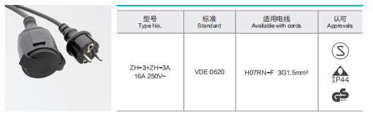
Global data centers must adapt seamlessly to regional plug standards. Terminating high-amperage IEC connections requires localized hardware assemblies. A C19 connector often pairs directly with a 16A European power cord for deployments in Frankfurt, London, or Amsterdam. Standard wall-side terminations include Schuko CEE 7/7 or heavy-duty IEC 60309 Commando plugs.
EU data center deployments require strict, documented compliance. Maintain CE and VDE certifications on file for all regional power assemblies. The wire gauge must meet European standards, typically utilizing 3x1.5mm² or 3x2.5mm² copper conductors. Failing to provide certified localized cords delays hardware deployment and violates local electrical codes. When shipping racks internationally, remove the North American NEMA cables and replace them with the correct European equivalents before the hardware leaves the staging area.
Decision Framework: Choosing the Right Power Cord for Your Infrastructure
Power Cord Types Comparison Chart
Use the following matrix to quickly reference the operational limits of core IEC connectors. Never exceed the stated amperage or temperature ratings.
Connector Type | Max Amperage (Intl / NA) | Max Pin Temperature | Pin Orientation | Physical Keying |
|---|---|---|---|---|
C13 (Female) / C14 (Male) | 10A / 15A | 70°C | Vertical | Chamfered top corners |
C15 (Female) / C16 (Male) | 10A / 15A | 120°C | Vertical | Bottom center notch |
C19 (Female) / C20 (Male) | 16A / 20A | 70°C | Horizontal | Rectangular, incompatible with C13/C15 |
Feature-to-Outcome Evaluation
Evaluating power draw against environmental heat drives correct selection. Use a strict decision matrix for facility upgrades and new hardware deployments. The rule of thumb remains straightforward and non-negotiable. Standard IT equipment requires the C13 connector. High-heat environments demand the C15 connector. High-power, high-density hardware necessitates the C19 connector.
Never compromise on these baseline rules. Attempting to save budget by using standard cables on high-heat switches results in inevitable hardware failure. Map the power draw of every device in the rack. Calculate the total amperage load and ensure the selected cables provide at least a 20% overhead margin for safety. If a server draws 12A continuously, do not use a cable rated for exactly 12A. Upgrade to a higher gauge wire to reduce resistance and heat generation along the cable run.
Scalability and PDU Compatibility
Standardizing connections impacts long-term facility scalability. Modern rack PDUs often feature C13/C19 combo receptacles. This hybrid approach future-proofs racks for changing hardware demands. You can plug a standard server into the receptacle today, and upgrade to a high-density blade chassis tomorrow without replacing the entire PDU. This flexibility reduces downtime during hardware refresh cycles.
Cable management requires careful, calculated consideration. Thicker gauge cords like the C19 require significantly larger bend radii. Forcing tight bends against the rack frame damages the internal copper conductors and creates electrical resistance. Bulky cables also impact rack airflow. Poorly routed high-amperage cables block exhaust fans, potentially increasing ambient temperatures and forcing the need for C15 upgrades elsewhere in the rack. Always use vertical cable managers and D-rings to support the weight of heavy C19 cable bundles.
Procurement Risks: Counterfeits and Non-Compliant Cables
Purchasing uncertified cables based on price alone introduces massive operational risk. Counterfeit cables flood the market, often utilizing dangerously undersized wire gauges. Manufacturers might use AWG 18 wire inside a thick jacket when AWG 14 is strictly required for the load. This deceptive cost-cutting measure creates severe fire hazards under peak data center loads. The jacket may look robust, but the internal copper cannot handle the current.
Always look for required, verifiable certifications. Ensure every cable carries UL, CE, VDE, and RoHS stamps on the packaging and the jacket. Verify the physical markings printed directly on the cable jacket before installation. If a cable feels unusually light or lacks printed specifications, discard it immediately. Protecting million-dollar IT infrastructure requires certified, tested power delivery components.
Implement a strict procurement checklist for your facility:
Verify the UL file number printed on the cable jacket against the online UL database.
Check the AWG or mm² rating stamped on the wire to ensure it matches the required amperage.
Confirm the temperature rating (e.g., 75°C, 105°C) aligns with the deployment environment.
Inspect the molded connectors for physical defects, flash, or loose pins.
Conclusion
Power cord selection remains a critical safety and operational decision for any IT environment. It is never a generic commodity purchase to be delegated without oversight. The C13 serves the reliable baseline for standard IT loads. The C15 solves specific, dangerous thermal challenges in network closets. The C19 enables the high-density power delivery required by modern blade architecture. Shortlist your cables using a strict, documented logic path. Audit the equipment power draw first to determine amperage needs. Assess environmental temperatures second to rule out thermal degradation. Verify regional plug compliance last to ensure legal and safe facility integration.
Take the following actions to secure your infrastructure:
Audit your current PDU connections today to identify and replace any existing thermal mismatches.
Map the total amperage draw of your highest-density racks to ensure your C19 cables and branch circuits have a 20% safety margin.
Standardize your procurement process to reject any cables lacking verifiable UL, CE, or VDE jacket stamps.
Consult with a power infrastructure specialist to design a scalable PDU layout using C13/C19 combo receptacles.
FAQ
Q: Can I plug a C15 power cord into a C14 inlet?
A: Yes. The C15 connector is fully backward compatible with a standard C14 inlet. The specific notch on the C15 simply occupies empty space, allowing it to fit into lower-temperature inlets safely. However, a standard C13 cord cannot physically plug into a high-temp C16 inlet, preventing dangerous thermal mismatches.
Q: What is the difference between a C13 and C15 power cord?
A: The primary difference involves the temperature rating and physical design. A C13 cord handles a maximum pin temperature of 70°C. A C15 cord handles extreme heat up to 120°C. Physically, the C15 features a distinct notch at the bottom center to prevent incorrect mating with lower-rated cables.
Q: When should I use a C19 power cord instead of a C13?
A: Use a C19 connector when equipment draws more than 10A to 15A. High-density hardware like blade servers, enterprise UPS systems, and high-capacity PDUs require the sustained high-amperage delivery that only a C19 cord can safely provide without overheating or causing voltage drops.
Q: Are IEC power cords universally compatible globally?
A: The equipment-side connectors, such as C13, C15, and C19, are universal across all regions. However, the wall-side plug must match local grid standards. For example, deploying high-amperage equipment in Europe requires terminating the cable with a localized, certified European plug to meet regional compliance.
Q: How do I verify the safety rating of a power supply cord?
A: Check the physical markings printed directly on the outer cable jacket. Look for the specific wire gauge, typically listed in AWG or mm². Verify the maximum temperature rating and ensure the presence of recognized regulatory stamps like UL, CE, or VDE to confirm authenticity and safety.
Q: Can I use a C13 extension cord to reach a distant PDU?
A: You can use a C13 to C14 jumper cord, but you must account for voltage drop over distance. Extending the cable run increases electrical resistance. If you must run a cable longer than 10 feet, upgrade to a thicker wire gauge, such as 14 AWG, to maintain safe power delivery.


