
Power Cable vs Power Cord Key Differences Explained
Views: 0 Author: Site Editor Publish Time: 2026-09-01 Origin: Site


Misclassifying electrical transmission components during the procurement or design phase routinely leads to code violations, premature equipment failure, and severe safety hazards. The terms "cable" and "cord" are frequently used interchangeably in general discourse. In electrical engineering and facility management, they represent fundamentally different product categories. They possess distinct regulatory standards, ampacity limits, structural anatomies, and installation requirements. Treating them as identical components creates immediate vulnerabilities in both temporary setups and permanent infrastructure.
This guide breaks down the technical distinctions between a power cable and a power cord. It provides a framework to evaluate specifications, ensure NEC and IEC compliance, and select the correct component for both temporary equipment and permanent infrastructure. By understanding the structural and regulatory differences, facility managers and electrical designers can eliminate specification errors, ensure safe power delivery, and maintain strict adherence to international electrical codes.
Installation Permanence: Power cables are engineered for fixed, permanent, high-capacity installations, whereas power cords are designed for temporary, flexible, and portable connections.
Anatomy and Termination: Power cords are complete assemblies featuring a plug, a flexible length of cord, and an equipment coupler/connector. Power cables typically feature bare wires intended for hardwiring, splicing, or custom lug termination.
Capacity and Shielding: Power cables generally support significantly higher voltage and current loads, utilizing robust jacketing and shielding for harsh environments, compared to the standard consumer or IT loads handled by power cords.
Regulatory Compliance: Substituting a flexible power cord for permanent power cable wiring violates standard electrical codes (like the NEC) and voids facility insurance policies.
Defining the Baseline: Power Cable vs. Power Cord
What is a Power Cable?
A power cable acts as the foundational infrastructure for electrical transmission. It consists of an assembly of one or more electrical conductors, typically held together with an overall protective sheath. Engineers design these assemblies for permanent installation and bulk power transmission across facilities, underground networks, and overhead lines. You will find them routed through rigid galvanized steel (RGS) conduit, buried in subterranean PVC trenches, or suspended from high-voltage utility poles.
These components handle heavy industrial machinery, main service panels, and facility-wide distribution networks. Installers pull these lines from large wooden spools and cut them to exact lengths on-site. Electricians then hardwire the bare conductors directly into breaker panels, junction boxes, or heavy equipment terminals. This process requires stripping the heavy insulation, applying anti-oxidant compounds to aluminum conductors, and securing the connection using specialized mechanical lugs or hydraulic compression fittings. Once installed, these lines remain stationary for the lifespan of the building or equipment.
What is a Power Cord?
A power cord serves as a temporary, flexible bridge between a device and an electrical utility. It is a pre-assembled length of flexible wire specifically designed to connect appliances, IT hardware, and portable equipment to a wall outlet or power distribution unit (PDU). The standard anatomy includes a molded male plug on one end for the utility connection and a female connector or equipment coupler on the other end.
Cords prioritize flexibility and user safety during frequent handling. They are not infrastructure. They simply deliver power from the permanent infrastructure to the end-use device. If a piece of equipment needs to be relocated, the user unplugs the cord, moves the device, and plugs it into a new receptacle. Manufacturers build these cords with integrated strain relief at the connector joints to prevent the internal wires from tearing loose during repeated plugging and unplugging cycles.
Disambiguation: Internal Power Supply Cables
Terminology overlap causes frequent confusion, particularly in the IT and computer hardware sectors. Technicians often refer to internal DC wiring—such as ATX, PCIe, and SATA connections—as "power supply cables." These components connect a power supply unit (PSU) directly to motherboard components inside a computer chassis or server enclosure.
While colloquially called cables, they operate under entirely different low-voltage DC standards. They do not carry facility-level AC power. They are distinct from the external AC power cords that plug the chassis into the wall, and they bear no structural resemblance to the heavy-duty infrastructure wiring that powers the building itself. Mixing up these terms during procurement can lead to purchasing incorrect components for server rack deployments.
Core Technical Differences and Evaluation Dimensions
Installation Permanence and Flexibility
Physical construction dictates the intended permanence of the installation. Conductor stranding plays a major role in defining this physical behavior. Cords utilize high-strand-count copper wire, often utilizing Class K or Class M stranding. A single 10 AWG flexible cord conductor might contain over 100 individual hair-thin copper strands. This incredibly fine stranding maximizes flexibility, portability, and resistance to metal fatigue from repeated bending and coiling.
Infrastructure wiring uses solid core conductors or lower-strand-count wire, such as Class B or Class C stranding. A 10 AWG building wire typically contains just 7 thicker strands. This design minimizes electrical resistance over long distances and provides structural rigidity. Stationary routing does not require high flexibility. Bend radius limitations differ significantly between the two. Forcing a rigid infrastructure line into a tight bend risks damaging the insulation, creating micro-tears, and establishing a thermal hotspot. Conversely, subjecting a flexible cord to constant physical tension or crushing weight will sever the fine internal strands, leading to a dangerous increase in electrical resistance and potential fire hazards.
Voltage and Ampacity Ratings
Voltage thresholds clearly separate the two categories. Power cords generally cap at 120V to 480V, matching standard consumer, commercial, and light industrial equipment needs. The insulation thickness on a standard cord is relatively thin, designed only to protect against low-voltage arcing and casual physical contact.
A permanent electrical line easily handles medium to high voltage applications. Standard building wire is typically rated for 600V or 1000V, while utility-scale distribution lines range from 5kV up to 35kV or more. Ampacity represents the maximum current a conductor can carry continuously without exceeding its temperature rating. This metric depends heavily on the installation environment. Conductors enclosed in fixed conduit or buried underground retain heat. Electricians must apply strict ampacity derating calculations based on NEC Chapter 9 tables when pulling multiple lines through a single pipe. Flexible cords operating in open air dissipate heat more effectively, but they lack the thick insulation and sheer copper mass required to handle massive, continuous current loads safely.
Anatomy, Termination, and Coupler Standards
The termination ecosystem highlights the functional divide between temporary and permanent solutions. Power cords rely on standardized plugs and couplers designed for rapid, toolless connection. In North America, NEMA configurations (such as 5-15P for standard outlets or L6-30P for locking industrial connections) dictate plug shapes based on voltage and amperage. Globally, IEC 60320 standards define the couplers used for IT and data center equipment, such as the ubiquitous C13/C14 and C19/C20 pairings. European markets utilize CEE standards to achieve the same plug-and-play functionality.
Infrastructure terminations require specialized skills and permanent hardware. Electricians use mechanical lugs, hydraulic compression fittings, and complex heat-shrink or cold-shrink splice kits. Terminating a 500 kcmil line requires a hydraulic crimping tool capable of delivering 12 tons of force to permanently bond the copper to the lug. These connections demand precise torque specifications, specialized crimping dies, and certified personnel to ensure a secure, low-resistance joint that will not degrade over decades of continuous use.
Technical Feature | Infrastructure Wiring | Flexible Cords |
|---|---|---|
Primary Application | Permanent facility wiring, high-voltage transmission | Temporary equipment connection to a utility outlet |
Conductor Stranding | Solid core or low-strand (Class B, C) | High-strand count (Class K, M) for flexibility |
Termination Method | Hardwired via mechanical/compression lugs | Pre-assembled NEMA, IEC, or CEE plugs/couplers |
Voltage Capacity | Medium to High Voltage (600V to 35kV+) | Low Voltage (120V to 480V) |
NEC Governance | NEC Article 310 (Conductors for General Wiring) | NEC Article 400 (Flexible Cords and Cables) |
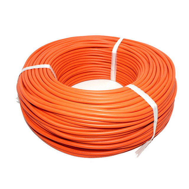
Application-Specific Selection Criteria
Industrial and Renewable Energy Infrastructure
Harsh environments demand specialized infrastructure lines capable of withstanding extreme physical and environmental stress. Renewable energy sectors present unique challenges that standard commercial wiring cannot survive. Solar arrays require a dedicated photovoltaic cable (PV wire) to connect individual panels to combiner boxes and central inverters. PV wire features robust cross-linked polyethylene (XLPE) insulation, providing exceptional UV resistance, extreme temperature tolerance, and direct burial ratings. Standard building wire like THHN degrades rapidly under constant sunlight and weather exposure, leading to ground faults, arc flashes, and total system failures.
Grid-scale battery facilities require a specialized energy storage cable to connect large inverter systems to the main grid. These lines must maintain absolute thermal stability while handling massive, continuous DC voltage loads (often up to 1500V DC) during peak charge and discharge cycles. They require specific flame-retardant properties to prevent fire propagation within dense battery containers.
Inside the battery banks themselves, UPS systems and telecom backups rely on a heavy-duty battery cable. This specific variant combines high-amperage capacity with a highly stranded core. Unlike rigid building wire, this flexibility allows installers to route thick conductors through the tight confines of battery cabinets without placing undue mechanical stress on the delicate battery terminals. The insulation on these lines is also formulated to resist degradation from battery acid and extreme localized heat.
Consumer, IT, and Portable Equipment
Data centers, medical facilities, and commercial offices rely entirely on flexible cords for final equipment connections. In high-density server racks, cord retention systems and locking IEC couplers prevent accidental disconnections caused by server vibration or routine maintenance bumps. The jacket type dictates the cord's durability in specific environments.
SJT (Service Junior Thermoplastic) works perfectly for standard office equipment and desktop computers. It handles light duty applications where physical damage is unlikely. SOOW (Service, Oil-resistant inside and out, Water-resistant) provides the ruggedness needed for portable tools on a factory floor. The heavy rubber jacket resists harsh chemicals, cutting fluids, and physical impacts from dropped tools or foot traffic. Medical environments require hospital-grade cords, identified by a Green Dot certification. These specific cords feature solid brass prongs and enhanced internal grounding reliability to protect sensitive patient-care equipment from power fluctuations and ensure a secure connection in fast-paced emergency rooms.
Compliance, Safety, and Regulatory Standards
NEC, UL, and IEC Code Requirements
Regulatory bodies draw a hard, uncompromising line between temporary and permanent wiring. The National Electrical Code (NEC) Article 400 explicitly governs the use of flexible cords. It strictly prohibits using a flexible cord as a substitute for the fixed wiring of a structure. Installers cannot run cords through holes in walls, structural ceilings, suspended ceilings, or floors. They cannot conceal them behind building panels or attach them permanently to building surfaces. Doing so traps heat, prevents proper thermal dissipation, and exposes the soft jacket to hidden physical damage from rodents or structural shifting.
Underwriters Laboratories (UL) provides distinct testing and listing standards for each category. UL 62 covers flexible cords and fixture wires, testing specifically for repeated flexing, twisting, and physical abrasion. UL 44 and UL 83 cover thermoset and thermoplastic insulated building wires. These standards focus on long-term thermal aging, dielectric strength, and flame propagation in fixed, stationary installations. Using a UL 62 listed cord in a UL 44 application is a direct code violation.
Environmental Ratings and Jacketing
Jacket material determines the environmental survivability of the electrical line. Polyvinyl Chloride (PVC) offers a reliable baseline for indoor, general-purpose routing. Cross-linked Polyethylene (XLPE) provides superior moisture resistance and high-temperature performance, making it the standard for underground and heavy industrial infrastructure. Rubber and Polyurethane jackets dominate the flexible cord market due to their elasticity, oil resistance, and ability to withstand crushing impacts on shop floors.
Fire safety ratings dictate indoor infrastructure routing. Lines routed through HVAC return air spaces require a plenum rating (such as CMP) to ensure low smoke production and minimal toxic gas release during a fire. Vertical runs between floors require a riser rating (such as CMR) to prevent flames from traveling up elevator shafts or conduit pathways. Flexible cords do not carry these structural fire ratings, further reinforcing the NEC prohibition against running them through walls or ceilings.
Jacket Material | Common Application | Key Properties |
|---|---|---|
PVC (Polyvinyl Chloride) | Indoor building wire (THHN), light duty cords | Cost-effective, flame retardant, moderate flexibility |
XLPE (Cross-linked Polyethylene) | Underground feeds, solar arrays, high voltage | High heat resistance (90°C+), excellent moisture barrier |
EPR (Ethylene Propylene Rubber) | Industrial infrastructure, medium voltage lines | Highly flexible at low temperatures, corona resistant |
CPE / SOOW Rubber | Heavy duty portable cords, factory floors | Oil resistant, abrasion resistant, water resistant |
Implementation Risks and Mitigation Strategies
Common Specification Errors
Specification errors occur when engineers misunderstand the environmental demands or the intended permanence of the installation. Over-specifying involves deploying heavy, armored infrastructure lines for a simple, protected indoor run. This wastes labor hours on difficult, rigid terminations that were entirely unnecessary. Pulling armored MC (Metal Clad) wire through a space that only required standard EMT conduit and THHN wire drastically increases installation time.
Under-specifying poses a much greater safety risk. Deploying a standard flexible cord across a high-traffic industrial floor subjects it to forklift traffic, chemical spills, and severe physical abrasion. The fine internal strands will eventually break, increasing electrical resistance and creating a severe fire hazard at the point of damage. Similarly, ignoring thermal derating represents a critical engineering error. When installers bundle multiple infrastructure lines in a single conduit or enclosed cable tray, the conductors cannot dissipate heat effectively into the surrounding air. Engineers must calculate the conduit fill capacity and apply strict derating factors to the ampacity limits. Failing to reduce the allowable current load leads to insulation melting, phase-to-phase short circuits, and catastrophic system failure.
Operational Downtime and Maintenance Trade-offs
Selecting the wrong transmission component directly impacts facility uptime and complicates maintenance workflows. Hardwiring portable or frequently swapped equipment with rigid building wire makes routine maintenance incredibly labor-intensive. Every equipment swap requires a certified electrician to execute full Lockout/Tagout (LOTO) procedures at the breaker, unbolt the mechanical lugs, and re-terminate the connections on the new device. This turns a five-minute equipment swap into a multi-hour maintenance event, driving up labor costs and extending operational downtime.
Conversely, relying on flexible cords for permanent, heavy-duty applications invites severe regulatory scrutiny. Electrical inspectors will immediately flag NEC Article 400 violations, leading to failed inspections, halted operations, and mandatory rewiring projects. Improper use of temporary wiring for permanent loads voids facility insurance policies. If a fire originates from an illegally concealed flexible cord, the insurance provider will investigate the code violation and deny the claim. Proper specification aligns the physical component with the operational workflow, ensuring safety, compliance, and efficient maintenance.
Conclusion
The choice between a permanent infrastructure line and a flexible cord is dictated entirely by the permanence of the installation, the required electrical load, and the termination method. Cords are pre-terminated, flexible assemblies designed for temporary equipment access and user mobility. Cables are raw, rigid infrastructure designed for permanent facility wiring, high-voltage transmission, and stationary system integration.
If the equipment moves, requires frequent disconnection, or plugs into a utility wall outlet via a standardized coupler, specify a flexible cord. If the wiring goes through walls, runs underground, connects heavy stationary machinery, or involves renewable energy generation, specify permanent infrastructure wiring.
Take the following steps to ensure compliance and safety in your next installation:
Audit your current project schematics to ensure no flexible cords are specified for routing through walls, ceilings, or floors in violation of NEC Article 400.
Calculate the exact ampacity requirements for your permanent installations, applying all necessary derating factors for conduit fill and ambient temperature.
Evaluate the environmental stressors of your installation site to select the appropriate jacket material, such as XLPE for outdoor solar arrays or SOOW for industrial shop floors.
Consult with a certified electrical engineer to verify termination methods and request technical specification sheets for all required infrastructure components.
FAQ
Q: Can a power cord be used as permanent wiring?
A: No. The National Electrical Code (NEC) strictly prohibits using flexible power cords as a substitute for fixed building wiring. Running them through walls, ceilings, or floors creates severe fire hazards due to a lack of physical protection and improper thermal dissipation. They are designed exclusively for temporary equipment connections.
Q: What is the difference between a battery cable and a standard power cable?
A: A battery cable is a specific type of infrastructure wiring designed for low-voltage, high-amperage DC applications. Unlike standard rigid building wire, it features a highly stranded copper core. This provides the flexibility needed to route thick conductors through tight spaces, like UPS cabinets, while maintaining heavy current capacity.
Q: What is an IEC coupler on a power cord?
A: An IEC coupler, such as a C13 or C19, is the standardized female connector on the equipment end of a flexible cord. It allows hardware manufacturers to sell a single device globally. Users only need to swap the wall-plug side of the cord to match their specific regional utility outlets.
Q: Are power cables and power cords regulated by the same standards?
A: No. While both fall under broad testing organizations like UL or IEC, they follow different specific standards. Flexible cords typically follow UL 62, which tests for repeated flexing and abrasion. Permanent building wiring follows standards like UL 44 or UL 83, which focus on long-term thermal aging and dielectric strength.
Q: Why do flexible cords use finely stranded copper wire?
A: Finely stranded copper wire maximizes flexibility and portability. When a cord is repeatedly bent, coiled, and moved, solid core wire would quickly suffer from metal fatigue and snap. High-strand-count wire withstands this constant physical manipulation without breaking or losing electrical conductivity.
Q: What does a plenum rating mean for electrical wiring?
A: A plenum rating (such as CMP) indicates that the wire's insulation is certified for use in building spaces that handle environmental air, like drop ceilings or raised floors. Plenum-rated jackets are designed to produce very little smoke and release minimal toxic fumes if exposed to fire.


