Arc Welding Electrode Cable Buying Guide: Key Specs You Must Know
Views: 0 Author: Site Editor Publish Time: 2026-05-05 Origin: Site


Selecting the correct welding cable goes far beyond making a simple electrical connection. It represents a critical mathematical calculation. This foundational choice protects expensive power supplies from thermal damage while actively mitigating severe fire risks across the shop floor. Many purchasing managers frequently overspend on unnecessary heavy gauges. Conversely, they undersize cables based on fundamentally flawed length estimates. This specific oversight directly causes preventable equipment downtime and introduces hazardous voltage drops during critical fabrication steps. You need a reliable, repeatable method to match cable specifications perfectly to your actual daily operational demands.
This guide gives you a transparent, evidence-oriented framework for sizing, selecting, and evaluating these vital physical attributes. You will learn exactly how to calculate total continuous circuit lengths and decode complex copper stranding standards. We will also help you navigate the nuances of synthetic insulation types. Applying these objective rules ensures lasting safety, strict regulatory compliance, and peak welding performance across all your heavy-duty industrial applications.
Key Takeaways
Total Circuit Length Dictates Gauge: Sizing calculations must account for the entire loop—adding both the electrode cable and the work (ground) cable together.
Stranding Determines Flexibility: The choice between Class K and Class M stranding directly impacts operator fatigue and cable lifespan in high-motion environments.
Insulation Matters: EPDM and Neoprene jackets offer distinct chemical and thermal resistances; standard electrical wire PVC is an inadequate and dangerous substitute.
Ampacity is Dynamic: Cable capacity fluctuates based on duty cycle, total length, and ambient temperature (typically rated for 75°C to 105°C).
The Core Differences: Arc Welding Electrode Cable vs. Standard Electrical Wire
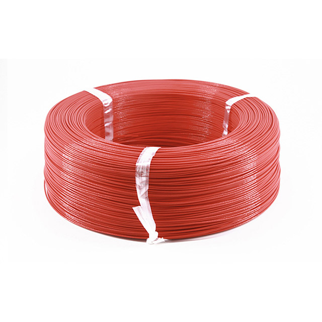
Arc welding inherently requires the constant physical manipulation of the electrode holder. Standard building Electrical Wire uses thick, rigid copper strands designed for permanent installation inside walls. These solid conductors restrict movement heavily. They break easily under repetitive flexing during complex daily fabrication tasks. You need specialized flexibility for these operations. Authentic welding cables feature hundreds of highly fine copper strands. Manufacturers typically use 30 AWG or 34 AWG micro-strands to achieve this necessary, repeated pliability.
Insulation realities present another stark contrast between these two distinct categories. Standard wire relies on hard PVC jackets meant purely for stationary conduit use. Welding environments demand much tougher materials. Cables require specialized synthetic elastomers like EPDM or Neoprene. These tough synthetic rubbers easily withstand constant dragging across abrasive concrete. They safely resist hot flying sparks and endure heavy industrial crushing from passing forklifts.
Watch out for a very common and dangerous purchasing trap. Substituting a cheaper automotive battery cable or standard power wire for an authentic Arc Welding Electrode Cable immediately voids expensive equipment warranties. It introduces severe safety hazards to your operators. Standard products simply lack the compatible thermal thresholds required to handle sustained welding currents safely over long shifts.
The 3-Factor Formula for Sizing Your Welding Cable
Ampacity represents the absolute maximum current a cable safely transmits without deteriorating its internal insulation. Proper sizing requires a strict three-variable assessment. You must calculate these specific factors carefully to determine the correct American Wire Gauge (AWG) size. Before diving into the specific variables or consulting a chart, always gather these three core data points directly from your equipment:
The accurately measured length of your entire welding loop.
The peak amperage rating found stamped on the welder's nameplate.
The listed duty cycle percentage operating at maximum output.
1. Total Welding Circuit Length
Many operators mistakenly only measure the straight distance from the welding machine directly to the workpiece. This represents a fundamental and dangerous miscalculation. The electrical circuit forms a complete continuous loop. You must combine the physical length of the electrode cable and the work (ground) cable together.
For example, using a 50-foot electrode lead and a 50-foot ground lead equals a 100-foot total circuit. Electrical current must travel all the way out to the weld puddle and all the way back to the machine to complete the process. When you double the physical distance, you essentially double the conductive resistance. Longer loops naturally require thicker cables to combat this inherent electrical resistance and prevent damaging voltage drops. Ignoring the ground cable length remains the most common sizing error in modern fabrication shops.
2. Maximum Amperage Output
Always match your cable size to the highest possible output of your welding machine. Do not base this critical decision solely on your average daily operating current. If you typically weld at 150 amps but your machine can output 250 amps, size the conductor for the full 250 amps. An undersized cable bottlenecks the power flow severely when operators eventually push the machine to its limits.
This forced electrical resistance causes the copper core to overheat rapidly. Operating continuously under these constrained conditions potentially damages the machine's sensitive internal circuitry. It also degrades the protective elastomer jacket from the inside out, creating invisible safety hazards.
3. Equipment Duty Cycle
Duty cycle represents the precise percentage of a 10-minute period the machine operates continuously before it overheats and shuts down. For example, a 60% duty cycle means six solid minutes of active welding followed by a mandatory four minutes of cooling. Higher amperage outputs usually operate at noticeably lower duty cycles.
A cable can occasionally handle amperages slightly above its baseline continuous rating if the duty cycle remains extremely short. However, continuous high-duty-cycle operations demand a much thicker gauge to dissipate accumulated heat safely. When automated robotic welders run at a 100% duty cycle, they require substantially larger cables than manual stations running at identical amperages.
Decoding Copper Stranding: Class K vs. Class M Standard
Industrial manufacturing standards divide conductor flexibility into two primary stranding classes. Choosing correctly impacts both operator ergonomics and long-term operational longevity. The specific way copper behaves under repeated bending defines the lifespan of your setup.
Class K Stranding (Standard Industrial):
Class K cables consist of 30 AWG individual copper strands. Depending on the total cable gauge, hundreds of these strands bundle together tightly. They offer standard flexibility suitable for most basic shop and field environments. This standard option remains highly cost-effective for general construction use. It serves as the recognized baseline expectation for commercial welding applications worldwide.
Class M Stranding (High-Flexibility):
Class M cables feature much thinner 34 AWG copper strands. Because each individual strand is thinner, manufacturers must bundle thousands of them to reach the exact same overall gauge. They deliver superior flexibility compared to the standard class. This enhanced pliability significantly reduces operator wrist fatigue during long manual shifts. It also proves invaluable for complex out-of-position welds inside tight spaces like pipe interiors. Class M typically carries a premium price point. Manufacturers often distinguish these highly flexible premium cables using high-visibility jacket colors like bright orange or green.
Evaluation Criteria:
Evaluate your specific daily application carefully. If the job involves high-speed robotics or extreme repetitive human motion, you should strongly invest in Class M. The operational return on investment justifies the higher upfront price through heavily reduced physical wear and far fewer sudden cable replacements.
Stranding Class Comparison Table | |||
Stranding Type | Copper Strand Size | Flexibility Level | Best Application Scenario |
|---|---|---|---|
Class K | 30 AWG | Standard | General shop fabrication, stationary bench setups |
Class M | 34 AWG | High/Superior | Robotics, long manual operator shifts, tight structural spaces |
Insulation and Jacketing: Matching Specs to Environmental Risks
You must verify the jacket’s specific thermal rating strictly before purchasing. Industrial safety standards mandate thermal thresholds of 75°C, 90°C, or 105°C. Operating in high-ambient-temperature facilities, like un-air-conditioned summer shipyards, inherently lowers the effective ampacity of any conductor. High external heat prevents the copper core from shedding its internal electrical heat efficiently. You must deliberately choose the right synthetic elastomer based on these environmental risks.
EPDM (Ethylene Propylene Diene Monomer):
EPDM rubber is a highly durable material. It offers excellent resistance to tearing, mechanical abrasion, extreme weather fluctuations, and constant water exposure. This rugged physical profile makes EPDM the best overall choice for general construction sites, structural steel framing, and outdoor fabrication yards. However, EPDM degrades quickly when repeatedly exposed to certain industrial hydrocarbons.
Neoprene (Chloroprene Rubber):
Neoprene shares the basic physical toughness found in standard EPDM. However, it adds crucial chemical resistance to oil, heavy grease, open flame, and petroleum-based fluids. This unique chemical profile makes it the absolutely mandatory choice for specific harsh environments. Automotive shops, oil pipelines, and heavy machinery repair facilities require Neoprene to prevent rapid jacket swelling and chemical degradation.
AWG vs. Metric Systems: Removing Sourcing Friction
Sourcing a proper Arc Welding Electrode Cable requires accurate gauge translation across different geographic regions. The American Wire Gauge (AWG) system follows a strict inverse rule. Smaller numbers mean thicker cables. Sizing typically ranges from #4 at the smaller end up to #4/0 at the largest end. Industry professionals pronounce #4/0 as "four aught".
For global compliance or when operating imported equipment, you must cross-reference the exact cross-sectional area. The metric system measures this functional area in square millimeters (mm²). Do not confuse standard metric Electrical Wire sizing with dedicated AWG welding formats, as the stranding requirements remain vastly different.
AWG to Metric Cross-Reference Chart | ||
AWG Size | Approximate Metric Equivalent (mm²) | Typical Continuous Ampacity Range |
|---|---|---|
4 AWG | 25 mm² | Up to 100 Amps |
2 AWG | 35 mm² | Up to 150 Amps |
1/0 AWG | 50 mm² | Up to 250 Amps |
2/0 AWG | 70 mm² | Up to 300 Amps |
Future-Proofing Logic:
Sometimes your sizing calculations place you hovering directly between two distinct sizes on a manufacturer's chart. Always default to the thicker cable showing the smaller AWG number. This simple practice provides built-in redundancy for future equipment upgrades. It also actively minimizes resistance heat during unusually long welding sessions.
Implementation Risks and Maintenance Protocols
Damaged external jackets or frayed internal copper strands drastically increase localized electrical resistance. This structural damage creates dangerous hot spots along the line. These isolated spots will quickly melt surrounding insulation and cause localized fires on your floor.
Connection integrity plays a massive role in overall performance. A perfectly sized cable remains completely useless if connections at the electrode holder sit loose. Heavily oxidized grounding clamps also bottleneck current flow significantly. Inspect these vital junction points daily before striking an arc.
Operators must actively avoid common coiling risks. Running a welder while the excess cable remains tightly coiled induces a strong electromagnetic field. This physical configuration traps heat rapidly inside the spool. It artificially lowers the ampacity and causes rapid, irreversible insulation degradation.
Establish firm replacement triggers for your entire shop. Cables exhibiting deep surface cracks, chemical swelling, or exposed internal copper must be replaced entirely. Do not attempt to simply tape over structural damage. Taping hides the underlying electrical resistance issue without solving the thermal danger.
Conclusion
Base your procurement strategy strictly on the fundamental 3-factor sizing model. Always evaluate your total circuit length, maximum machine amperage, and equipment duty cycle simultaneously. Evaluate specific environmental hazards at your facility to choose accurately between EPDM and Neoprene jackets. Assess daily operator fatigue levels to decide between Class K and Class M copper stranding.
Take immediate action by auditing your current power supplies to determine their maximum output and specific duty cycle. Measure your maximum required workspace reach accurately, ensuring you account for the return path. Finally, consult a standardized ampacity chart before issuing any new purchase order to guarantee long-term safety and operational efficiency.
FAQ
Q: Does the polarity (DC+, DC-, or AC) change the size of the cable I need?
A: No. Polarity only affects the welding characteristics, penetration profile, and electrode selection. It does not alter the physical gauge required to carry the electrical current safely.
Q: Can I use heavy-duty battery cable instead of welding cable?
A: No. While they look similar and carry high currents, battery cables use rigid PVC meant purely for stationary automotive applications. They lack the extreme flexibility required for welding and will rapidly degrade or break when dragged across shop floors.
Q: Why is my #4 welding cable overheating even though my machine is set below 100 amps?
A: Overheating usually occurs because the total circuit length exceeds safe limits for a #4 gauge at that specific amperage. It may also stem from a corroded connection causing hidden resistance, or operating well beyond the cable's designed duty cycle limit.


